
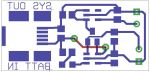
Ok i was tired of using stupid batteries and having to recharge off board. So i decided to make a LiPo charger but with a nice 300mA 3.3v regulator on board.
I have not made it yet tho… i just finished the design and schematics and so far its nice and small and should work fine!
The LiPo charging will be controlled via MCP73831
The 3.3v @ 300mA out will be regulated using … MCP1802
Seems like they both are Microchip parts and have same foot print which is a SOT-23-5.. slightly bigger than a normal SOT-23.. since it has 5 pins instead of 3…
I would love some comments…


I have always thought the two battery charger projects at this site looked interesting. They also use a graphical LCD.
http://oshonsoft.com/picprojects.html
Jay
Cool. Those are NiCd/NiMH chargers… i like LiPo since there are so thin! heh and lighter
Hi! I am new to electronics and I am a bit confused about the symbol coming off of pin 1 on the MCP1802 and pin 3 on the 73831. What is the symbol that is tying these pins to 5V? Is this a diode of some sort? It is the symbol labeled U$4. I looked at the typical circuit on the MCP1802 datasheet and it just shows supply voltage tied to pin 1. Thanks in advance!
Yeah 2 schottky diodes or a BAT54C:
Click to access BAT54C.pdf
What this does is allow 2 voltages to pass in 1 direction so they wont interrupt each other. So i can power from multiple places
So the diode allows you to get 3.3V from the battery (normally ~3.7V?) or 3.3V from USB while also charging the battery? Is the max current available in both cases or just when powering the circuit from USB? Just wanted to make sure I get this straight before I etch one of these. Thanks again for answering my questions, and for putting this circuit together!
I recommend using a BAT54C because the Vf is low.. max is 800mV … What will you use this for ? just powering a project of just charging a LIPO ? I recommend not connecting it the way i did. The Vf will be to much for the Regulator if your using >10mA i didnt even notice that.
I suggest building either 2 seperate parts, 1 charger and 1 regulator or make a charger with a boost circuit using a NCP1402. Real simple and cheap.
Well eventually I wanted to incorporate it into a bare bones Arduino/ RN-42 Bluetooth combo for a home brew Android game pad, but if the regulator maxes out around 10mA I will have to rethink that. The RN-42 uses around 45mA by itself when transmitting according to the data sheet. I haven’t even gotten around to calculating the Arduino power requirements yet. Honestly this is all still in the early stages, I don’t even have a circuit on a bread board yet.
its not the regulator but you can create remove the BAT54C and replace with a switch for charge position and play position and will work flawless
Nice idea…
Check this out:

Bummer, having the battery charge while still using the gamepad would have been a killer feature. I definitely need a steady 3.3V for the bluetooth, happily I can run an Arduino at 3.3V as well (running at 8 Mhz on internal oscillator). Thanks for putting together that second schematic so fast!
So wait…the boost circuit you mentioned with the NCP1402…I would drop that in place where the diodes are now, and also disconnect the 5V from the USB obviously. Any reason why that set up couldn’t charge and play at the same time? Sorry for all the questions, digital logic/ software is fine but when I get into the power requirements my head spins! Thanks
Dont be sorry, yeah with boost you should be able to do both.. ill make a schematic
Dont be sorry, yeah with boost you should be able to do both..
Man you rock! Thanks for all the help on this. I’m probably going to get a few of these made at Batch PCB or maybe seeed studio. Let me know if you want one and I’ll gladly ship it your way.
Cool, ill take one heh.. have you heard of DorkBotPDX ?
http://dorkbotpdx.org/wiki/pcb_order
They are very cheap! and good.
Yeah I had heard of them a few months back but I still haven’t tried them out. I think I’ll give them a go this time around though. You can e-mail me at ian (period) kephart AT gmail (dot) com if you want a copy of the board. Thanks again!
Happened on this thread after a google search looking pretty much for the same thing… I do have a question. If 3.7v is coming from the LIPO battery and we want 3.3v regulated output why do we need a boost regulator? Also what value is the inductor in that circuit? Thanks in advance.
OK the inductor is 47uH. The reason for the boost is the diode drops the 3.7v to 3v.
I see… Is there any benefit to the NCP1402 approach as opposed to using an LDO regulator such as the MIC2505 such as in this schematic if all you need is 150mA:
Yeah the boost regulator will run from 0.8v and supply 3.3v